Thursday, 7 May 2015

New control unit

As a simple plan I thought the 4 different colour LEDs could correspond to 4 different frequencies of sound. So red for the base, green for low mid-range, blue for high mid-range and white for above this.

This can be achieved using a low-pass, 2 band pass and a high-pass filter.

There are a few ways of doing this, active, passive or maybe using an ADC on a micro controller.

Active

This is basically filtering with amplification, but effective decoupling is provided if OpAmps are used.

Passive

This is very basic CR ladders, may be sufficient for our needs.

Analogue to digital

Could use the ADC input of a PIC to switch signal to a different port when a certain frequency threshold is reached? TBH this is my preferred solution as it involved the least amount of components and doing digital is sooo much easier even if the PIC is programmed in assembler - which is very cool, but I will probably use C for simplicity.

In all cases the 12V can be switched using transistors - old fashioned analogue things, but can be used as a switch so very very useful!


Flashing lights

So the lights under the bar top flash, how hard would it be to get them to flash to music! If you read this blog in chronological order it will make more sense now!

Looking at the input to the light strip we have a 12V supply line and 3 other lines.

There is a control box that connects to the LED strip and controls which lights come on and when.

I plan to replace this control box with my own control box that either plugs into a music source or has it's own mic to pick up ambient sound.

LED strip under the bar top, with remote control senser


Connector to LED strip

BBQ

Obviously this blog wouldn't be complete without mentioning the BBQ!


Here we have a cooking equipment, a BBQ and outdoor hob.

Electrics

We're nearly at the point of this blog!

The electrics. On the old bar I had 12V decking lights above the bar, which provided a very weak light and were just enough when it was dark. The new bar has much better lighting using a 240V supply makes it far more extendible.

A spur was taken off the garage supply fed through a hole in the wall.

Plug socket installed.
For lighting I decided to go for LEDs, these are very effective, low power and suitable for outdoor use. I got them from Lighting Ever (www.lightingever.co.uk) which have a good selection of LED 'strips' at a very reasonable cost. These are single LED of a certain colour spaced 3cm apart.

The lighting above the bar was stuck to a wooden rectangle suspended from the apex of the roof, this ensures light is thrown on the bar top and the BBQ.


Each LED strip is 5M in length, I had to use 2 strips here.

Connectors for lights

Under the bar I put green LEDs to give the effect of the whole thing floating!

Under bar - also shows 240V plugs for lighting.
Under the bar top I put coloured LEDs that can be changed with a remote control. These lights are RGB and white and can show a multiple of colours and can be set to flash or fade and even programmed.

 Under bar top showing red.


 Under bar top showing blue.


In case you were wondering what happened to the rest of the shed. It can be seen in the background here, rearranged into a 1/4 size shed.

Also shown above are the 4 barstools I bought second hand for £30. I now have seating for 6 :)

Remote control for under bar top lights

Bar top

This is the most important and time consuming part of the bar construction.

The old bar was simply a bit of old kitchen worktop I happened to have in the garage, I had grander ideas for the new one.

The bar is 105cm high - a standard height, with an overhang of 20cm, the minimum to eat comfortably at.

The bar is made of 18mm ply, which in theory should be strong enough to support a 20cm overhang without too much flex, but I wasn't convinced and found it seemed to flex a little too much under load.

By the time I'd built the top I had decided to tile it with small mosaic tiles, but it turns out that these are really expensive and my money-no-object plan was blown out the water. Also in the evening the sun shines directly into the bar and the reflection off the sample mosaic 'gloss' tile is blinding.

Holding the top in place before screwing down.

The width of the bar is 50cm, this seems ample given the space available.

At this point I painted the sides using a bathroom waterproof paint, that I had left over from another DIY job, on top of a white undercoat.
Top screwed in place and sides painted

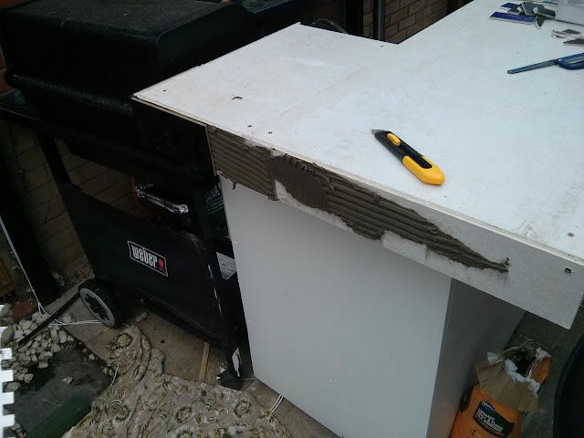
The 6mm backing board is called "No More Ply" and is very rigid and hard. I used a tile scorer to cut it in a score and snap way. The score needs to be quite deep to get a good break. This was glued and screwed to the 18mm ply and forms a very rigid structure.

Backing board added.
I have never tiled before, but it turned out to be very simple!
First tile added

Tiling finished with mat black tiles (to minimise glare when it's sunny) a grey grout.

Tiling all finished

Wednesday, 6 May 2015

Building the bar

This is the design showing the bar framework. Note the gap at the back for the hatch - all bars need one of these!
Bar top and panels removed to show frame

This is made of ordinary stud-wall timber - it shouldn't get too damp, all measurements as per original design. The difference between designing on the PC and doing it for real is that bits of wood don't hover in the air when you let go of them, it'd be so much easier if they did - maybe someone should invent a wood hovering environment.

First section.

The ground that it is being built on is not level so I have incorporated an adjustable foot on each upright, this is also so that damp does not wick up the legs. This is simply a recessed screw thread and a dome-topped bolt.

Adjustable feet can be seen on legs
Bar frame finished, left out additional right-of-hatch bit for now.

View from back of bar

As the wood is untreated I decided to paint it in green fence preservative just in case it gets damp.


Cladding placed on bar, with filler to hide the gaps


View from the other side


Sanded off and ready for painting


After putting this is place and sitting on a stool, then standing behind the bar, I realised that there was more room behind the bar than in front, which didn't look quite right and it would mean that the seats were quite close to the wall, especially considering that there is a 20cm overhang on the bar-top.

Soooo, I decided to cut 30cm out of the width, what's that motto, measure once, cut twice, or something like that!

A little adjustment

Now with the re-cut cladding on. Mistakes at this stage are a lot easier to fix!!

30cm narrower, no room for hatch :(


It started with a wendy-house...

I have built a BBQ & bar in my garden, this replaces the old bar that I built a few years ago, which replaced the wendy-house-on-stilts. This blog is actually about installing the disco lights underneath it, but there was quite a bit of work done first...

I didn't blog this as I went along, but you'll get the idea hopefully.

Several years ago I build my kids this wendy-house, on stilts so I can get the mower in and out of the shed behind. As they got older they used it less and less, in fact I'm not really sure they used it that much at all, so I decided to knock it down and build a BBQ/bar/outdoor kitchen, utilising as much of the old wendy-house materials as possible.

The wendy-house
So keeping cost cost down in case we never really got round to using it much I built this, some of the wood is reused as planned. Well it turned we used this bar loads, for parties, family gatherings, regular meals, breakfasts throughout the spring and summer.
The Old Bar
The problem with this bar is that it is too small, with seating for only 2 or 3 people. What is needed is a bigger bar (still with BBQ of course).

As you can see, behind the bar is still the shed, full of junk and gardening stuff, this will need to go to extend the bar area backwards.

First job is to relocate the shed (18th Feb 2015), but I have nowhere that would accommodate the size (10' x 6'), only option available is to chop it in half and put it round the back of the garage...

Dismantling the shed

OMG - that's only half of it

Half shed placed round other side of garage
Now (half) the shed is relocated I have a lot more space...

The other side of the old bar with more space

Next job is to remove the old bar roof as I want to put the full width of the area under cover.

I've never really done this type of thing before and being a bit of a geek I sat down at my computer and came up with this design in Sketchup....


Using Sketchup is quite simple but the reality of placing timber in mid-air whilst attaching other bits of wood is quite different!

Old bar removed and new temporary roof timber supports in place.
I extended the frame, made from ordinary fence posts, and placed it against both walls.
The upside down T-shaped bits of wood are to hold the ridge board in place whilst I attach the rafters. The pitch on the roof is 30º, all initial measurements coming from the Sketchup design.

Ridge board on the supports
Now that the ridge board is in screwed in place I can start attaching the rafters. These were first cut slightly over size as the two walls aren't exactly parallel like I'd assumed in my Sketchup design. They were clamped in place before being screwed.
Front and back rafters
Old bar being used as a work bench, and to stand on to work on the rafters!

At this stage the roof was a bit wobbly so was braced in place - this is all pressure treated timber so should last.

Brace
In case anyone is wants to know this is created using a compound mitre cut of 45º and 30º on one end and a 30º cut on the other. I didn't really realise I needed to do this until I was doing it, and this is why the chop-saw has a rotation and a lean angle - it worked a treat anyway.

The rest of the rafters were cut to size - each one slightly different. Again this was done by cutting them too long, then trimming until the exact fit is achieved.
All rafters nearly in place.
 Purlins in place on one half of one side to hold the perspex roof.

Purlins - still need to be cut.

As there is no overhang the guttering needs to be internal and this is the reason the rafters are attached to the inside of the frame and not the more usual top.
End of Gutter for one side
The perspex roof being fixed in place and the finished roof - note the upside down gutter on top to make it kinda waterproof.
Putting perspex sheets in place - this was very hard work!

Finished roof with a bit of rain.